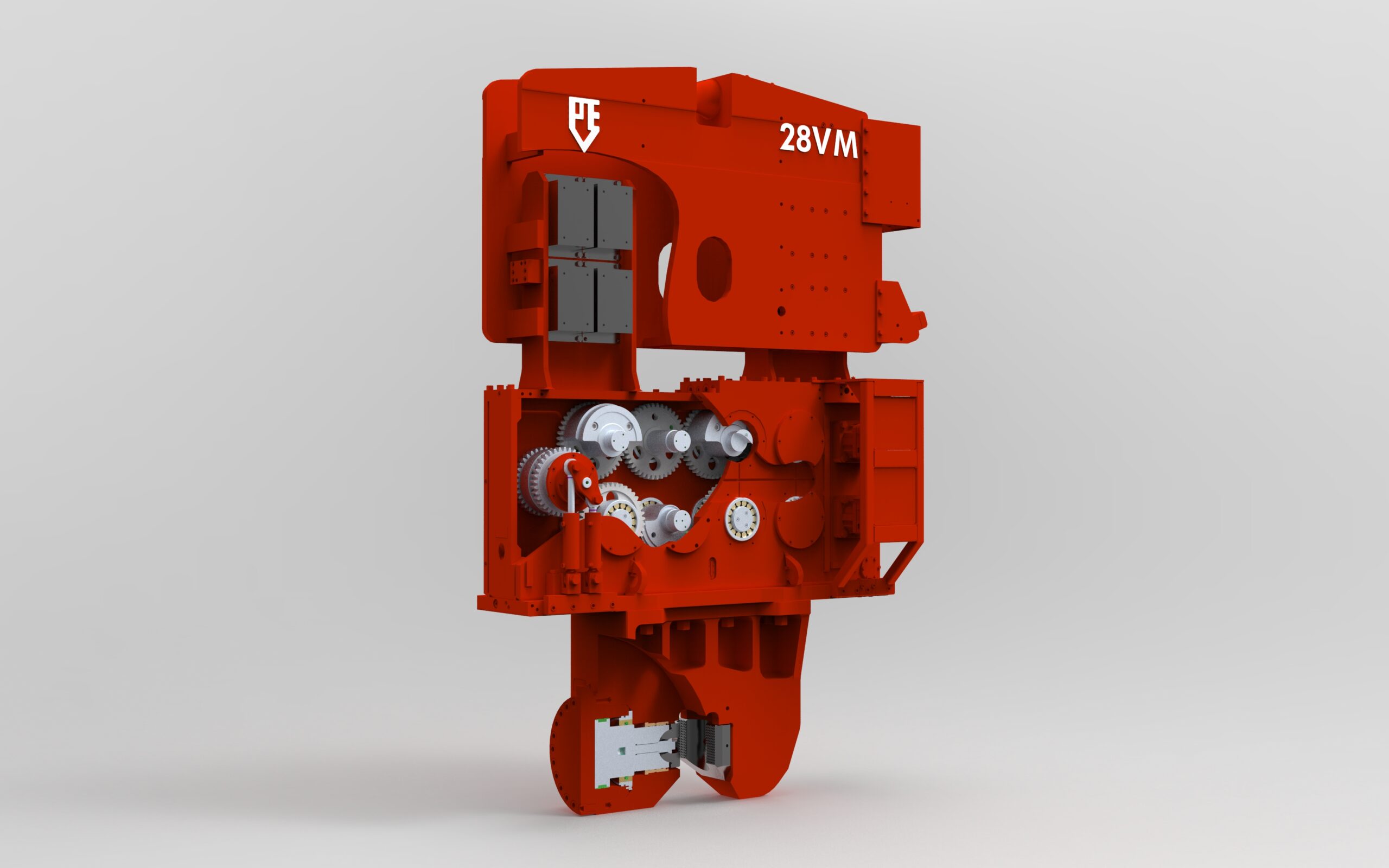
The vibratory hammer is a mechanical sine-wave oscillator with weights rotating eccentrically in opposite directions so that their centripetal actions combine in the vertical direction (pile axis direction), but cancel out in the horizontal. The effect of the vibrations is an oscillating vertical force classified to frequency and amplitude.
Vibratory hammers work by eliminating soil resistance acting on the pile. The vibrations generate pore pressures which reduce the effective stress in the soil and, therefore, the soil shear strength. The process is more effective along the pile shaft as opposed to the pile toe and works best in loose to compact silty sandy soils, which do not dilate and where the pore pressure induced by the cyclic loading can accumulate (where the dissipation of water pressure is not immediate).
When a hammer impacts on a pile head, the force, or stress, transferred to the pile builds progressively to a peak value and then decays to zero. The entire event is over within a few hundreds of a second. During this time, the transfer initiates a compression strain wave that propagates down the pile at the speed of sound (which speed is a function of the pile material—steel, concrete, or wood). At the pile toe, the wave is reflected back toward to the pile head. If the pile toe is located in dense soil, the reflected wave is in compression. If the pile toe is located in soft soil, the reflection is in tension. Hard driving on concrete piles in soft soil can cause the tension forces to become so large that the pile may be torn apart.
That pile driving must be analyzed by means of the theory of wave propagation in long rods has been known since the 1930s. The basics of the mathematical approach was presented by E.A. Smith in the late 1950s. When the computer came into common use in the early 1970s, wave equation analysis of pile driving was developed at the Texas A&M University, College Station, and at the Case Western Reserve University, Cleveland. Computer software for wave equation analysis has been available to the profession since 1976.
During the past two decades, a continuous development has taken place in the ease of use and, more important, the accuracy and representativeness of the wave equation analysis. Several generations of programs are in use as developed by different groups. The most versatile and generally accepted programs are GRLWEAP and Allnamics.
The wave equation analysis starts the pile driving simulation by letting the hammer ram impact the pile at a certain velocity, which is imparted to the pile head over a large number of small time increments. The analysis calculates the response of the pile and the soil. The hammer and the pile are simulated as a series of short infinitely stiff elements connected by weightless elastic springs. Below the ground surface, each pile element is affected by the soil resistance defined as having elastic and plastic response to movement an damping (viscous) response to velocity. Thus, a 20 metre long pile driven at an embedment depth of 15 metre may be simulated as consisting of 20 pile elements and 15 soil elements. The time increments for the computation are set approximately equal to the time for the strain wave to travel the length of half a pile element. Considering that the speed of travel in a pile is in the range of about 3,000 m/s through 5,000+ m/s, each time increment is a fraction of a millisecond and the analysis of the full event involves more than a thousand calculations. During the first few increments, the momentum and kinetic energy of the ram is imparted to the pile accelerating the helmet, cushions, and pile head. As the calculation progresses, more and more pile elements become engaged. The computer keeps track of the development and can output how the pile elements move relative to each other and to the original position, as well as the velocities of each element and the forces and stresses developing in the pile.
The damping or viscous response of the soil is a linear function of the velocity of the pile element penetration (considering both downward and upward direction of pile movement). The damping response to the velocity of the pile is a crucial aspect of the wave equation simulation, because only by knowing the damping can the static resistance be separated from the total resistance to the driving. Parametric studies have indicated that in most cases, a linear function of velocity will result in acceptable agreement with actual behavior. Sometimes, an additional damping called radial damping is considered, which is dissipation of energy radially away from the pile as the strain wave travels down the pile.
(Ref: Basics of Foundation Design, Bengt H. Fellenius 2021)


